Table of Contents
Signalling PrinciplesSignals
Main Signals
Shunt Signals
Main signals with a subsidiary signal
Automatic Signals
Replacement of Signals
Diverging Routes
Train Detection
Track Circuit Display
Signalling Principles
This section of the wiki is designed to introduce users to the principles behind UK signalling. If you are new to SimSig this section will explain the different components which we simulate within the simulations.
Signals
See also Signalling Display Symbols , Signal Aspects , Overlaps , Shunt Signals , Setting Routes , Types of Route .
Signals tell the driver what to do, and are controlled by the signaller. To clear a signal, the signalman must set a route from one signal to another. In SimSig, this is done by left clicking a signal (the 'entry' signal), and then left clicking the next signal along in the direction the train needs to be sent. Routes can be cancelled by right clicking the signal (depending on the options in the F3 list, you may have to select 'cancel' from a drop down menu. The track between one signal and the next is called a 'section' of track. There are 2 basic types of signal: Main and Shunt.
Main Signals
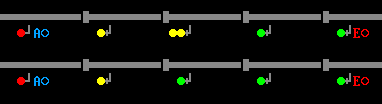
Main signals are shown by a coloured circle. These colours are called aspects , and are as follows:
| Colour | SimSig Indication | Meaning |
|---|---|---|
| Red |  |
Stop (with subsidiary ) |
| Yellow |  |
Caution, the next signal is showing a red aspect |
| Double Yellow |  |
Preliminary caution, the next signal is displaying a single yellow aspect |
| Green |  |
Clear, the next signal is displaying a proceed aspect |
| Flashing Yellow |  |
This indicates a lower speed diversion ahead but not severe enough to require approach release. The next signal will be showing a steady single yellow aspect. |
| Double Flashing Yellow |  |
This indicates a lower speed diversion ahead but not severe enough to require approach release. The next signal will be showing a flashing yellow aspect. |
| Flashing Green |  |
These were used in the Peterborough - Grantham section to indicate 140mph running. Although still displayed, these have no special indication anymore. |
Note that not all signals are capable of displaying all aspects, such as the double yellow aspect, and that buffers are treated as a red signal. Routes can only be set from main signals to main signals, unless the main signal has a subsidiary signal (see below).
Some signals have an R next to them. This means they are repeater signals, and cannot display a red aspect. They will show Yellow, or Green, depending on the aspect of the next signal ahead. Some repeater signals are also capable of showing double yellow. Repeater signals marked RR are only capable of showing double yellow or green; the next signal will be a standard repeater in this case. Routes cannot be set towards repeater signals, since they aren't capable of showing a Red aspect.
When a route is set to from a main signal to a main signal, not only must all the track between the first signal and the next be clear, but there must also be a length of track clear after the signal (the length is based on many factors), called the overlap . This is so that if the driver misjudges the braking approaching the signal, or is unable to stop at the signal for whatever reason, the train will not derail on any subsequent points or collide with any conflicting movements. Note that trains in SimSig will not pass signals at danger without permission.
3 and 4 aspect signalling
| SimSig indication | Type of signalling |
|---|---|
 |
4 aspect sequence 3 aspect sequence |
Shunt Signals
Also known as Position Light (PL) or, when situated at ground level, a Ground Position Light (
These signals are a quarter circle. Their aspects are as follows:
| Colour | SimSig Indication | Meaning |
|---|---|---|
| Red |  |
Stop |
| Yellow |  |
Stop, unless the route is not set in the direction for which the signal can be cleared (see below) |
| White |  |
Signal can be passed at caution towards the next stop signal or buffer stop |
In real life, red is shown by two horizontal red lights (or in older installations, one red and one white, the red on the left), and white is shown by two white lights, one above and to the left of the other. The signals are usually on the ground, as opposed to being mounted on a post like main signals (though the latter is sometimes seen). Yellow is shown as with red but, obviously, using yellow lights (so either two yellows or a yellow and a white).
Shunt signals with yellow lights are sometimes found at sidings where there is need for trains to move along the sidings and into the headshunt, but without proceeding onto the running line. The yellow indication means "stop if the points are set for a movement that would take the train on to a running line". Trains are permitted to pass the signal whilst it is displaying "ON" if the points are not set for the running line. The driver is expected to know which routes the signal has to be cleared for.
When a shunt signal is cleared (two white lights on the ground; a white triangle in SimSig) it permits the driver to pass the signal, and to proceed at caution being prepared to stop short of any obstruction. Unlike a main aspect, when a shunt signal is cleared it does not mean that the line is clear as far as the next signal.
Some shunt signals have LOS written next to them. This means that there is no route that can be set from the signal and no white aspect: it is there so that trains can back up for a short distance along a line that is not usually used in that direction, for example to access sidings or move from one platform at a station to another. In real life these "signals" used to be a signboard stating "Limit Of Shunt", which is the meaning of the "LOS" caption; these signs are no longer standard, but lots still exist on the network. The modern replacement is a shunt signal with no white lights.
Where a shunt signal is between two main signals, it's usually possible to set a route between the two main signals only. In this case, the shunt signal is known as a 'running shunt' or 'preset' and will clear automatically, however the driver will be obeying the aspect of the next main signal, and will not have to proceed slowly past each shunt signal as described above. The route should always be set between the main signals where possible, and passenger trains should only be routed between main signals.
Generally, routes set from shunt signals do not require overlaps .
Main signals with a subsidiary signal
| SimSig indication | Explanation |
|---|---|
 |
A main signal with a subsidiary shunt signal attached |
Automatic Signals
The paragraphs above deal with controlled signals, which require a route to be set for every train. In reality, most track is 'plain line' (away from points, certain types of level crossings, etc.), so automatic signals are used. Auto signals work themselves, with no action of the signaller, and display the relevant aspect based on whether the next section is occupied or not, and the aspect of the next signal. Some Automatic signals have a red button marked 'E'or 'R' next to them. This is so the signal can be set to danger (replaced) by the signaller in an emergency, or to protect certain level crossings (see separate topic).
Semi-Automatic Signals
A Semi-Automatic signal is an automatic signal that protects a ground frame or an emergency crossover. Releasing the ground frame will cause the signals to be replaced to danger (see separate topic).
Controlled Signals with 'A' button
Some controlled signals have a button that places them in automatic mode for a certain route, i.e. when a train passes it, it will re-set itself when the route has cleared again. These are used at junctions where one route is used more often than another, to save the signaller time. Don't forget to take the signal out of Automatic mode (by right clicking the button to make the circle hollow), before a train that requires another route approaches it. Note that taking the signal out of Automatic mode will not cancel the route set, until another train passes to clear the route. Some signals have more than one route that can be worked automatically.
Replacement of Signals
| Type | Description |
|---|---|
| First wheel replacement | This is where the signal will replace on the occupation of the first track circuit in advance of the signal. |
| Last wheel replacement | This is where the signal will replace on the release of the track circuit in the rear of the signal. |
Diverging Routes
Where there are routes from a signal to two or more signals, there will usually be a speed difference between the two routes (a diverging route usually having a lower speed than the direct route). Because the driver needs some warning of this, the signal is held at a more restrictive aspect than would otherwise be the case, and then clears to the expected aspect when the train approaches the signal. This technique is called approach control ; Flashing Yellows are used where the diverging speed is relatively high.
Train Detection
Train detection is essentially 'how do we know whether a section of track is occupied by a train?' Train detection is normally accomplished using Track Circuits. How this works is quite technical, so for the best explanation, please see this Wikipedia Article
Axle Counters are a different method of train detection which are becoming increasingly common in recent years, although examples have been used for a long time on some very long sections, or ones where track circuits are unreliable (for example in the Severn Tunnel). These essentially count the number of wheels entering a section, and the number leaving a section. If these values are equal, the section is assumed clear. In SimSig, the generic term Track Section is used to cover all types of detection.
If a section is occupied, the track is red instead of grey. To show section boundaries, in the F3 options menu, tick 'show track circuit breaks'. Note that a thick grey vertical line instead of the usual short gap shows the end of a signal's overlap . If a track circuit is occupied, you can not:
- Change any points covered by the circuit.
- Set another route over the track circuit, unless it is identical to the previous route.
- Raise any Controlled Level Crossing covered by the circuit.
- Any occupied track circuit in a route will set the entrance signal to danger (unless the route is a shunt route at a location where
call on routes are allowed.
Track Circuit Display
| Symbol | Meaning | |
|---|---|---|
 |
Track Circuit , not occupied by train | |
 |
Track Circuit occupied by train, or a track circuit that has failed* | |
 |
Track with route set | |
 |
Non-track-circuited track, or else track not controlled by your signalbox | |
 |
Siding where trains cannot enter/exit the Simulation | |
 |
End of Overlap (Show track circuit breaks turned On) | |
 |
Track under an engineer's possession |
Last edited by Sophira on 07/07/2022 at 17:42