
Page 1 of 2
| Power Supply (Signalling & Operation) 14/10/2013 at 05:11 #49951 | |
|
CTCThiago
232 posts |
Good Morning/Evening mates. So, let's try to make it simple. I create this topic to discuss and try to make clear how the the components of the signaling system (signals, track circuits, etc.) are powered electrically, and how can it affects the operation of trains. To make the train schedules, we have several items according to: - the availability of the fleet - passenger demand - track capacity - electrification capacity - signalling headway - and etc... But i wonder, how signalling devices are powered in ECML, I'm aware of the systems in place(25kV AC systems and it varies between 17.5 kV and 29kV), I don't know if i'm expressing myself as it should, but in simple, wanted to know the limitations of the system in a matter of operational capacity in accordance with the systems devices. Cheers, Thiago. 
Log in to reply |
| Power Supply (Signalling & Operation) 14/10/2013 at 09:36 #49953 | |
|
kbarber
1712 posts |
Signalling power supplies, as I understand it, are taken from the public electricity supply completely independent of traction power. Many of the older signalboxes on the network (probably the majority of Simsig boxes) actually consist of local interlockings controlled from a central panel through a multiplex system that allows multiple commands to be sent over a single pair of wires. If reliable safety-critical multiplexes didn't exist, each of those local interlockings would have been given a panel and would be a signalbox in its own right, so you could almost think of it as if it is a remote-controlled signalbox. Each of these local interlockings will have its own power supply arrangements, taken from a convenient feeding point in the local public system. But I think I'm right in saying there's also a signalling power supply network (600V AC? Have I got that right?) that covers the whole of a power signalled area. Whether that could be used to supply a local interlocking from the adjacent feeds on either side I don't know (I'm not even sure whether they're connected but I'm sure someone here will know). In addition to the feed(s) from the public supply, there will also be backup supplies. I have an idea it is possible to arrange feeds from two independent sections of the public supply (National Grid) system to any given location, so that if one fails the other is likely to remain live (unless the failure is particularly widespread). It's also common to have diesel generators available for backup; if the supply drops out the diesel starts automatically and takes the load as soon as it's able, leading to a brief outage (less than a minute I'd guess). And where there's electric traction I believe it's not unknown to arrange a backup supply from that source. So many boxes may have as many as four possible power supplies; it's not that likely that all will go down simultaneously. (Other things can go wrong though. Many years ago, contractors working at the lineside cut through the main power supply to Old Oak Common Panel - between the power supply compound and the box! Given the prevalence of 125mph traction on that route, a lot of drivers were reputedly rather unhappy when they suddenly found themselves confronted with an array of black signals! The outage affected the West London Line as well, with block failures extending as far as Kensington South Main.) In mechanical days, it wasn't uncommon for signalling supplies to consist of batteries (often wet cells in a cupboard beneath the box, in latter years more often banks of dry cells). Where there were motor points a hand generator would sometimes be provided rather than going to the expense of arranging a mains supply (which might be quite difficult in a remote country location). When colour light signals started to appear, signalling supplies would be arranged from the nearest suitable point but as they would be 600V transformed to 110V they weren't much use for anything else; at North Pole Junction, in spite of a good array of colour light signals, illuminated diagram, etc, the box remained gas lit in 1980 (and, as far as I know, until abolition in the early '90s). On the Midland Main Line, colour light signalling was installed between St Pancras and Carlton Road Junction in 1957. The signalman at Engine Shed junction (one Les Duffield) persuaded the S&T to hook up an electric light circuit, together with mains sockets, so Engine Shed became one of the first boxes on the line to have electric light. (The S&T had regularly to be persuaded to lose a few signal lamps too. Very persuasive man was Les.) In later years, it apparently sometimes happened that workmen at Engine Shed would see a mains socket and plug in their 240V drill (or whatever), promptly blowing the main signalling fuses. Generations of S&T, at first unwilling to drop their mates in it and later afraid of being blamed for not reporting it, got used to hurriedly beetling up from St Pancras to replace the Engine Shed fuses without letting anyone know what they were doing and why. Happy days... We've wandered a long way around the topic; hope that helps though. Log in to reply The following users said thank you: CTCThiago, Forest Pines, quickthorn |
| Power Supply (Signalling & Operation) 14/10/2013 at 11:56 #49960 | |
|
Stephen Fulcher
2029 posts |
The power supply arrangements differ widely. Generally, each location cabinet has 110v AC supplied to it somehow. In modern installations this is usually by means of a 650v supply transformed down in each cabinet. Older installations were often fed as 110v from a central location on long cables, spurring off to supply a busbar in each location. I have also seen 240v sent down a cable and transformed down to 110v locally. The 110v busbars in location cabinets can feed some equipment (such as signal heads) directly, or else transform down again, often to 50, 24 or 12 volts DC to feed other equipment. In older installations it is common for the 110v bars to feed battery chargers with banks of batteries for the DC components. There are also primary cells (batteries which cannot be recharged) to supply power for some indications back to the signal box in older installations. When these fail (go flat) they can cause a disproportionate amount of chaos. Log in to reply The following user said thank you: CTCThiago |
| Power Supply (Signalling & Operation) 14/10/2013 at 12:42 #49963 | |
|
clive
2739 posts |
" said:Actually, the multiplex doesn't have to be safety-critical, just like the signalling panel doesn't have to be. Taking King's Cross as the example I'm most familiar with, each interlocking is a separate safety-critical installation. Each has its own control panel, though this is normally locked out of use and isn't as "pretty" (for example, TCs with points flood red even when routes are set). Actions on the main panel are sent to the interlockings, whether local or remote, in the same form (e.g. "push button at S273"  and the interlocking turns that into route commands. The messages, and the resulting reports on TC and signal status, come over the multiplexes, which aren't safety-critical because they can't cause a wrong-side failure. and the interlocking turns that into route commands. The messages, and the resulting reports on TC and signal status, come over the multiplexes, which aren't safety-critical because they can't cause a wrong-side failure.
Log in to reply The following user said thank you: CTCThiago |
| Power Supply (Signalling & Operation) 14/10/2013 at 14:24 #49967 | |
|
CTCThiago
232 posts |
Thanks for the support mate's. I'm learning a lot here. Here in my state (Rio de Janeiro), the entire railway was built by the British workers, including the electrification of the system in 1937, with the contract signed on March 14, 1935, which came out in the magazine "The Metropolitan-Vickers Gazette". Part of the announcement: "When the economic history of Brazil is written, two dates making will stand out at the commencement of a new epoch in internal transport. On the 15th of May, 1934, HE the President of the Republic of Brazil signed a decree Authorising the electrification of Certain lines of the Central Railway by the Metropolitan-Vickers Electrical Company, Limited. On the 14th March, 1935, the contract was formally signed by officals of the Brazilian Government and the Metropolitan-Vickers Company. " How the system works: The power supply should be centered on substation "Deodoro" through current 80 kV three-phase 50 Hz, which would be transformed to 44 kV and distributed to five other substations. Overall consumption of the system, and also to each substation, substation was measured at "Deodoro". Nevertheless, this first phase supply ended up being done in this substation and also the another substation, with three-phase current of 25 kV to 50 cycles. Substations were then adapted to operate with both current 25 kV and 44 kV. should be noted that at the time the frequency of the alternating current was not standardized in Brazil and in Rio de Janeiro, was 50 cycles, only several decades after the national electrical system started to operate uniformly in 60 cycles. Each substation had three banks valves mercury vapor rectifiers, each with 2,500 kW, totaling 7,500 kW per substation, one of the banks was as reserves. Unique design of the Metropolitan-Vickers electrification was not fully implemented provided other three substations: Belém (Japeri), Martins Costa (Serra do Mar) and (Santa Cruz). The original project included the construction of 334 miles of overhead electrification of railway lines, including the stretch along route. As can be observed is more than double the nominal 147 km of lines, but we must also consider the passages with multiple lines and deviations. The stretch between D. Pedro II and Deodoro, for example, alternated with four or six sections lines. The overhead network consisted of simple catenary suspension with longitudinal; wire contact allowed compositions develop speeds up to 100 km/h (60mph), with the return circuit by own track. The poles, made of metal structure, should support not only the catenary to power the trains, as well as a double circuit 44 kV three-phase power supply to the substation and a single phase line of 4.4 kV for railway signalling. Sorry for the length of the words, just put out of curiosity. As described there on top here we have 4.4kV for signaling (track circuits, signals, etc. ...). In a matter of operation can not exceed 100km/h (60mph). I have another question: What is the maximum speed that the electrical system allows trains to develop on ECML? Thank you for your patience and understanding. Greatful Thiago. :cheer: Log in to reply |
| Power Supply (Signalling & Operation) 14/10/2013 at 16:06 #49972 | |
|
GeoffM
6292 posts |
" said:" said:To clarify, there is more than just "safety critical" and "not". There are a number of SIL (Safety Integrity Levels), though the railway typically uses three (I'll note right now that there are exceptions to this):Actually, the multiplex doesn't have to be safety-critical, just like the signalling panel doesn't have to be. 0: Not safety critical 2: Safety related 4: Safety critical Levels 1 and 2 are similar to each other, as are 3 and 4. An interlocking is SIL4; the control system is usually SIL2. I would imagine multiplexers are also SIL2. While multiplexers should not be able to directly cause the interlocking to do something nasty, anything talking to such needs to not provoke the interlocking - for example, automatic routesetting systems have their own ideas of what routes are available to set so it'll only ask the interlocking if it thinks the request will succeed. It'll also only try a route request three times before declaring the request a failure and turning off subareas. In addition, any multiplexer (and/or control system) needs to present timely and correct information, lest the signaller use misinformation to cause an unsafe situation, which again suggests more than than "not safety critical". SimSig Boss Log in to reply The following user said thank you: CTCThiago |
| Power Supply (Signalling & Operation) 14/10/2013 at 19:56 #49987 | |
|
Lardybiker
771 posts |
" said:I have another question: What is the maximum speed that the electrical system allows trains to develop on ECML?The OHL equipment used on the ECML is 25kV AC and is the same for the whole country where OHL is installed. The speed on a line is not limited by the electrical supply but rather the layout of the track in terms of how curvy it is. Most of the ECML is 125mph though there may be sections as high as 140mph (certainly the class 91 trains built specifically for the ECML were capable of 140mph at least but I don;t know if they were ever allowed to run that fast in normal service). The WCML used to be 110mph in places but since the WCML upgrades that may be places where it's quicker now especially with the pendalino's ability to lean round corners allowing the trains to traverse curves at a higher speed (think motorcycle going round a corner though it's not required the passengers stick their knees out!!). That said, there are people amongst us with better route and speed knowledge on the WCML and ECML than me who could tell you precisely about the speed limits. Going back to the electrical supply, the same overhead 25kV AC voltage is used throughout Europe too including in France where they use it on, amongst other things, the TGV routes. Some years ago they did some tests using a shortened TGV Atlantique set and managed a speed of 300mph give or take, back in the 90's and they were powered by the same 25kV from overhead cables just like the ECML uses so higher speeds are possible jus not witht he track layout the UK currently has. Log in to reply The following user said thank you: CTCThiago |
| Power Supply (Signalling & Operation) 14/10/2013 at 21:01 #49988 | |
|
postal
5197 posts |
" said:The OHL equipment used on the ECML is 25kV AC and is the same for the whole country where OHL is installed.Not strictly true. I can think of at least one section of track owned and operated by Network Rail which uses 1.5Kv DC OHLE (Pelaw to Sunderland on the Tyne and Wear Metro where the metro light railway trams share the tracks with conventional "heavy rail". “In life, there is always someone out there, who won’t like you, for whatever reason, don’t let the insecurities in their lives affect yours.” – Rashida Rowe Log in to reply |
| Power Supply (Signalling & Operation) 14/10/2013 at 21:08 #49990 | |
|
CTCThiago
232 posts |
" said:" said:I know the speed on the line has many factors to be imposed to a train (Track layout, Electrical system and more) my query is if the system has any restriction to impose more then 125 mph. But you explained as well, I understand.I have another question: What is the maximum speed that the electrical system allows trains to develop on ECML?The speed on a line is not limited by the electrical supply but rather the layout of the track in terms of how curvy it is. Different from here in Rio, the track layout on some parts, allows trains to run more then 100km/h (60mph) [The trains were built to reach 120km/h (75mph)] but the Overhead Line restricts to 100km/h (60mph) due to his particularity. I like to thank you, like i said above,  sometimes i don't expressed myself correctly, but i'm clarifying this. sometimes i don't expressed myself correctly, but i'm clarifying this. Greatful, Thiago. :cheer: Last edited: 14/10/2013 at 21:10 by CTCThiago Log in to reply |
| Power Supply (Signalling & Operation) 14/10/2013 at 21:14 #49991 | |
|
CTCThiago
232 posts |
" said:Thanks to clarify this section of SLI's Geoff :) Cheers, Thiago. :cheer: Log in to reply |
| Power Supply (Signalling & Operation) 15/10/2013 at 16:11 #50031 | |
|
Steamer
3929 posts |
" said:" said:Sounds like the amount of power required by the trains' motors to run at 75mph is more than the overhead wires can comfortably supply." said:Different from here in Rio, the track layout on some parts, allows trains to run more then 100km/h (60mph) [The trains were built to reach 120km/h (75mph)] but the Overhead Line restricts to 100km/h (60mph) due to his particularity.I have another question: What is the maximum speed that the electrical system allows trains to develop on ECML?The speed on a line is not limited by the electrical supply but rather the layout of the track in terms of how curvy it is. "Don't stress/ relax/ let life roll off your backs./ Except for death and paying taxes/ everything in life.../ is only for now." (Avenue Q) Log in to reply |
| Power Supply (Signalling & Operation) 15/10/2013 at 16:48 #50035 | |
|
Jan
892 posts |
It could equally be the mechanical design of the OHLE which is preventing higher speeds.
Two million people attempt to use Birmingham's magnificent rail network every year, with just over a million of them managing to get further than Smethwick. Log in to reply |
| Power Supply (Signalling & Operation) 20/10/2013 at 15:21 #50185 | |
|
Forest Pines
525 posts |
I have seen this given as the reason why Eurostar sets were limited to 110mph on the ECML despite being easily capable of running (and stopping) at the 125mph maximum line speed: a Eurostar set has a separate pantograph for each power car, and unlike LGV catenary, the ECML OHL couldn't cope with two raised pantographs so close together at full speed. The original APT design came up with a cunning way around the same problem: although the plan was foreeach train to have two power cars, the trains would have been a pair of half-sets "inside out" with the power cars together in the centre with a relatively short HV bus linking them on the supply side. I don't think this was ever fully implemented; and it meant each train needed twice the catering facilities and almost twice the staff. Log in to reply |
| Power Supply (Signalling & Operation) 20/10/2013 at 20:40 #50195 | |
|
postal
5197 posts |
" said:The original APT design came up with a cunning way around the same problem: although the plan was foreeach train to have two power cars, the trains would have been a pair of half-sets "inside out" with the power cars together in the centre with a relatively short HV bus linking them on the supply side.I heard at the time that the Railway Inspectorate had put a block on an HV bus passing over/through passenger carrying accommodation. “In life, there is always someone out there, who won’t like you, for whatever reason, don’t let the insecurities in their lives affect yours.” – Rashida Rowe Log in to reply |
| Power Supply (Signalling & Operation) 20/10/2013 at 22:37 #50199 | |
|
Forest Pines
525 posts |
" said:" said:Exactly, hence why they came up with the arrangement I described to power two power cars from a single pantograph, and why a Eurostar set requires two pantographs up.The original APT design came up with a cunning way around the same problem: although the plan was foreeach train to have two power cars, the trains would have been a pair of half-sets "inside out" with the power cars together in the centre with a relatively short HV bus linking them on the supply side.I heard at the time that the Railway Inspectorate had put a block on an HV bus passing over/through passenger carrying accommodation. Log in to reply |
| Power Supply (Signalling & Operation) 11/04/2014 at 11:21 #58692 | |
|
CTCThiago
232 posts |
Guys, I have some photos here of the Energy Control Center: 1. 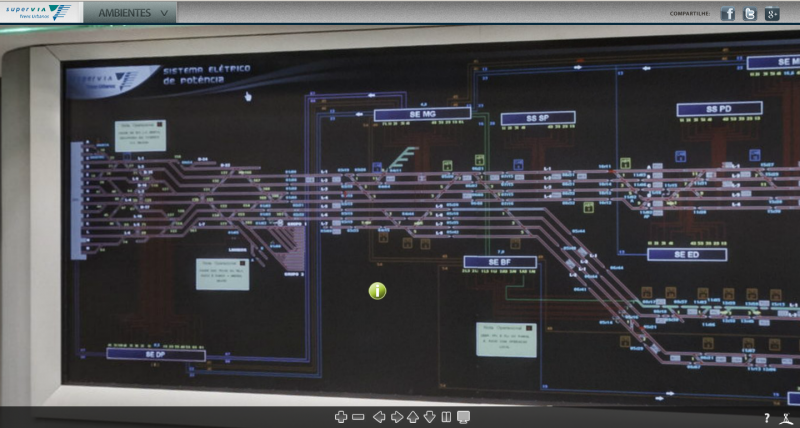 2. 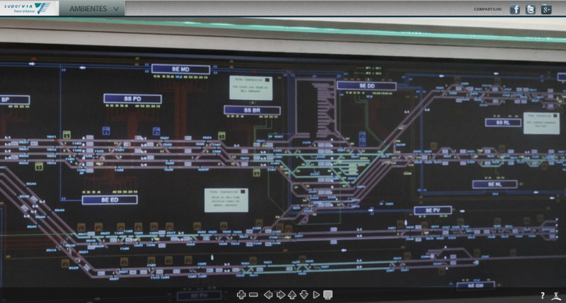 3.  Font: Supervia Website. Cheers, Thiago. Post has attachments. Log in to view them. Log in to reply |
| Power Supply (Signalling & Operation) 11/04/2014 at 11:29 #58693 | |
|
CTCThiago
232 posts |
And others too: 1. Old panel: 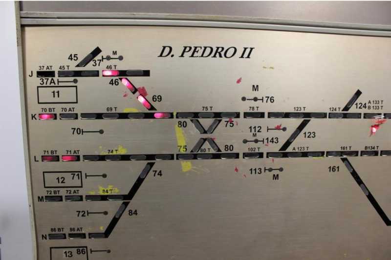 2. New panel: 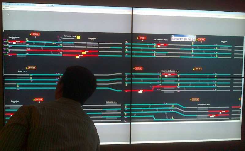 3. The Main City Terminal (Dom Pedro II) 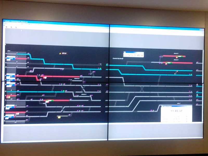 4. A Train Describer: 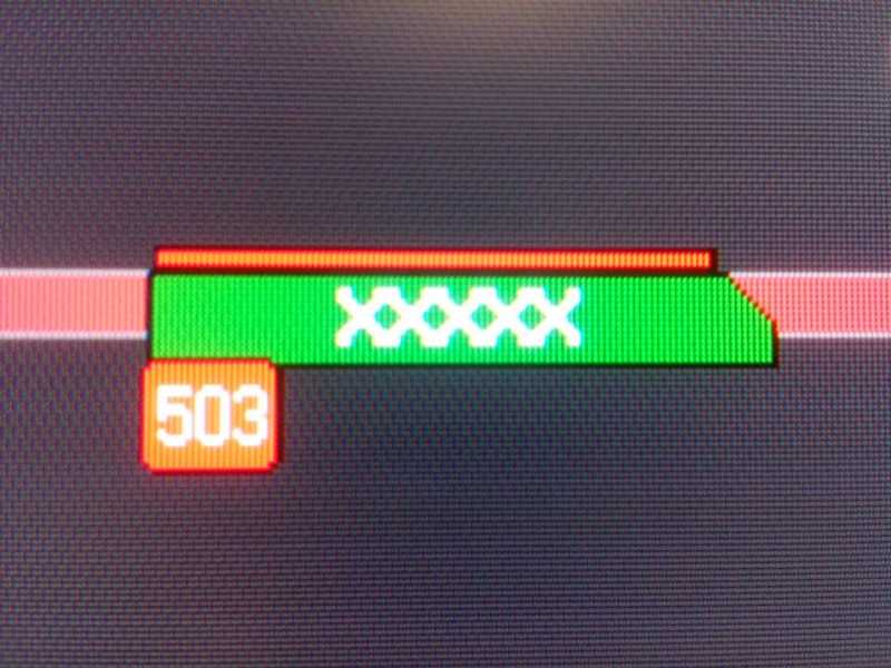 5. Old SSCT System, Today only used for supervision: 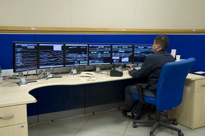 6. Workstations: 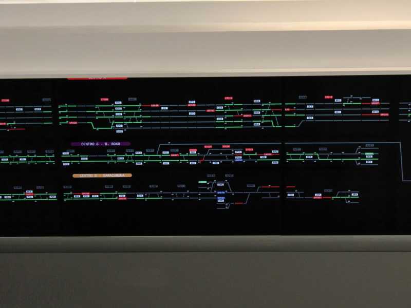 7. Planning Chart of Rolling Stock: 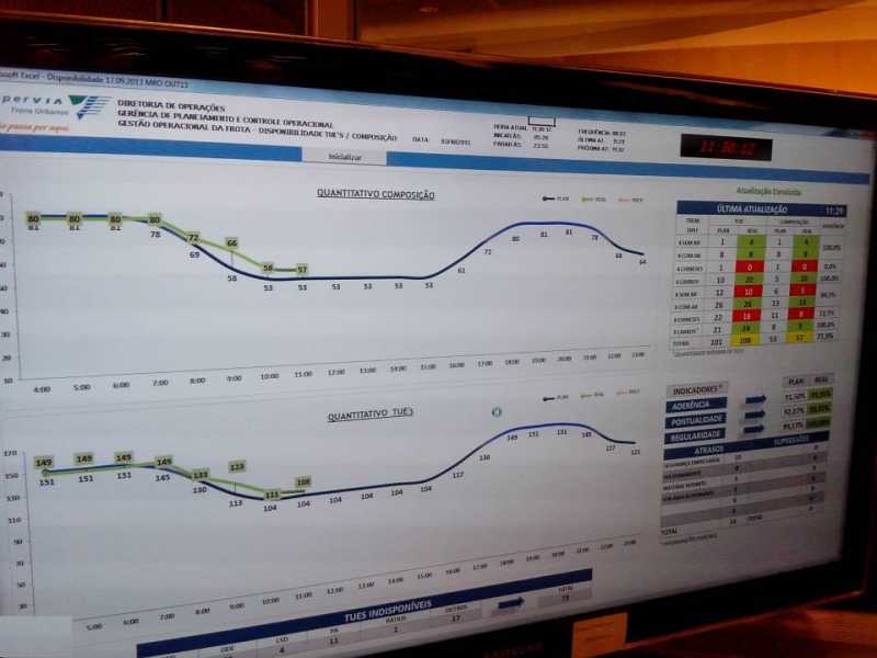 8.Signal Control Centre: 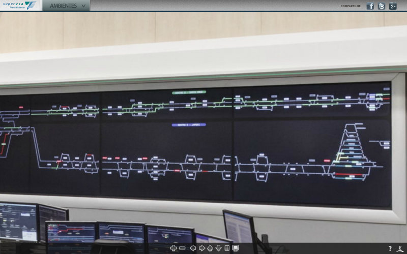 9.Signal Control Centre: 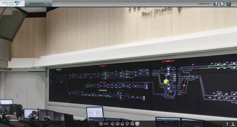
Post has attachments. Log in to view them. Last edited: 11/04/2014 at 11:39 by CTCThiago Log in to reply The following users said thank you: maxand, Firefly, Forest Pines, BarryM |
| Power Supply (Signalling & Operation) 11/04/2014 at 12:02 #58695 | |
|
Finger
220 posts |
Quote:Actions on the main panel are sent to the interlockings, whether local or remote, in the same form (e.g. "push button at S273"Oh really? The commands maybe can't cause wrong side failure, but the resulting reports certainly can! (eg. when a signalman allows a train to run through a set of points whose indication spuriously shows "normal" Without fail-safe indications, you can't have any oral authorizations or other standby measures, and no ERTMS RBC.
Log in to reply |
| Power Supply (Signalling & Operation) 11/04/2014 at 12:26 #58696 | |
|
Ron_J
329 posts |
Thanks CTCThiago for the interesting photos. By way of comparison, I've got some shots of the Network Rail electrical control room for Scotland on my site in case anyone's interested.
Log in to reply The following users said thank you: CTCThiago, bfcmik, Hawk777 |
| Power Supply (Signalling & Operation) 11/04/2014 at 12:55 #58697 | |
|
CTCThiago
232 posts |
" said:Thanks CTCThiago for the interesting photos. By way of comparison, I've got some shots of the Network Rail electrical control room for Scotland on my site in case anyone's interested.I'll check it out, If it is Railway, I'm interested!  Cheers. Log in to reply |
| Power Supply (Signalling & Operation) 11/04/2014 at 14:15 #58702 | |
|
Firefly
521 posts |
Quote:Oh really? The commands maybe can't cause wrong side failure, but the resulting reports certainly can! (eg. when a signalman allows a train to run through a set of points whose indication spuriously shows "normal"The local interlocking would prevent any signals being cleared over the points that are in the wrong position. If the signal failed to clear prior to authorising a train to pass the signal the signaller would key the points to the correct position. You are therefore looking at 3 independent failures on two separate systems which coincidentally has effected the same set of points. Failure 1) Points failed to move Normal when commanded by the route setting. Failure 2) Points failed to move Normal when keyed to Normal by the signaller. Failure 3) Points spuriously indicated Normal despite being reverse on the ground. The above is very improbable considering the Controls and Indications systems are separate. If the above did occur, the signaller would authorise the train to pass the signal and proceed at caution to the next signal and therefore any problems would occur at low speed. FF Log in to reply |
| Power Supply (Signalling & Operation) 11/04/2014 at 15:08 #58707 | |
|
headshot119
4869 posts |
" said:Quote:Is it not also in the rulebook that the driver has to check the position of any facing points?Oh really? The commands maybe can't cause wrong side failure, but the resulting reports certainly can! (eg. when a signalman allows a train to run through a set of points whose indication spuriously shows "normal"The local interlocking would prevent any signals being cleared over the points that are in the wrong position. If the signal failed to clear prior to authorising a train to pass the signal the signaller would key the points to the correct position. "Passengers for New Lane, should be seated in the rear coach of the train " - Opinions are my own and not those of my employer Log in to reply |
| Power Supply (Signalling & Operation) 11/04/2014 at 18:03 #58712 | |
|
GeoffM
6292 posts |
" said:Quote:Really. Technically "commands" to the interlocking from the signalbox (or office to field) are only requests since the interlocking won't act on them if it is not safe to do so. Comms to the interlocking are not safety critical, either in the UK or the US, and probably not in any other mainline railway.Actions on the main panel are sent to the interlockings, whether local or remote, in the same form (e.g. "push button at S273"Oh really? The commands maybe can't cause wrong side failure, but the resulting reports certainly can! (eg. when a signalman allows a train to run through a set of points whose indication spuriously shows "normal" SimSig Boss Log in to reply |
| Power Supply (Signalling & Operation) 11/04/2014 at 18:43 #58715 | |
|
Stephen Fulcher
2029 posts |
It is far more common for indications to fail completely rather than spuriously indicate something different to what is occurring on the ground. For instance, points not detected on the panel, even though they are on the ground, signal out on the panel but lit on the ground (although a TPWS fault can also cause this), track circuit showing occupied on the panel but clear on the ground. It is also possible (and I have seen it) for a signal controlled by a remote interlocking to be showing off on the panel, with a set of points in the route flashing out (but also indicating locked). On the ground they were correctly detected and locked by the safety side of the remote interlocking, but the indication TDM system had a fault which prevented the NWCR function being transferred back to the panel. This looks wrong, but is not unsafe. Log in to reply |
| Power Supply (Signalling & Operation) 11/04/2014 at 21:20 #58726 | |
|
clive
2739 posts |
" said:Greenhill Upper Junction, 22 March 2009. Points 125C failed to move Reverse when commanded by the route setting and when keyed Reverse by the signaller, and in both cases 125 indicated Reverse despite 125C being normal on the ground. In very very brief summary, there was a wiring error that meant that 125C merely needed to be locked and detected in either position (125A and 125B needed to be locked and detected in the correct position). And then track workers left points 125C in manual, rather than interlocking, mode. Thankfully it was that way round and the points were trailing to the first train to hit them in the wrong position (at 64 mph). If "normal" and "reverse" had been swapped in the above description, 125C would have been facing to a train doing 100 mph. Log in to reply |