Table of Contents
Semaphore SignallingIntroduction
Absolute Block
Clearing Points
Signalling Principals
Shunt Signals
Running Shunts
Junction Signals
Approach control
Short sections
Miscellaneous
Intermediate Block Sections (IBS)
Track circuiting
Available Routes
Semaphore Signalling
Introduction
SimSig was initially designed to simulate Multiple Aspect Signalling, with an IECC interface. However, over time, several simulations have been written which contain semaphore signalling. The exact method of implementation varies from simulation to simulation- some use standard colour light symbols, others use the special semaphore set. This page is intended as a guide, and to introduce users to the principals of Semaphore signalling. It is not an exhaustive guide- indeed SimSig’s replication of it is imperfect- however it provides a grounding in the basics. More extensive guides, and more accurate simulations, can be found elsewhere on the internet.
Absolute Block
Most SimSig simulations simulate ‘Track Circuit Block’. A block section is considered to be the track between two signals. Layouts are fully track circuited (excluding some sidings), and contains a high level of automation- the signaller sets routes, and the aspect of the signal is determined by the interlocking, depending on what track circuits are occupied.
Semaphore signalling is different. Most semaphore areas work under the Absloute Block system. Here, the block section starts at the last stop signal controlled by the first box, and ends at the first stop signal controlled by the second box. Movements within the section are controlled jointly by the two signalmen, using a series of bell codes.
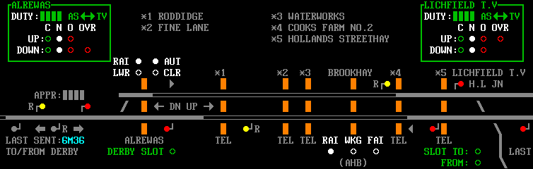
In SimSig, some simulations give you the option of simulating Absolute Block. The above image shows the block section from Lichfield T.V. Junction to Alrewas. Like most AB sections, it is not track-circuited.
Only a basic representation of AB is simulated in SimSig, and operating instructions can be found in Absolute Block manual .
For a full explanation of how AB works in reality, The Signal Box has a detailed, and accessible, guide.
Clearing Points
One element of AB which is relevant in SimSig is the Clearing Point. The Clearing Point is essentially an overlap, which must be clear before the signalman can accept a train from the preceding signal box. It is typically extends ¼ of a mile beyond the first stop signal, and may extend through subsequent signals.
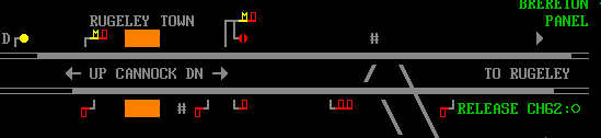
Clearing points, indicated by a # in this case, at Rugeley Town.
Details of clearing points can be found in the user manual. Often, they will be represented like a normal overlap, however in the case of CScot and NEScot, they aren’t, and penalty points are issued if a route is set with the clearing point fouled, or if the clearing point becomes fouled after the route is set.
Signalling Principals
On each line, a signalbox controls one or more stop signals, which show red or green, and a distant signal, which shows yellow or green. The distant signal is cleared when all the stop signals on a given line are clear. In real life, the distant signal is controlled by a separate lever, however in SimSig the distant is cleared automatically when the conditions for clearing it are met.
These days, most distant signals are colour light- as they’re located up to 1500 yards from the ‘box, this was a rather heavy ‘pull’ for the signalman! To avoid confusion with Repeater signals, colour light Distant signals are marked with a ‘D’.
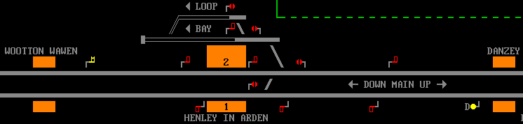
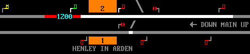
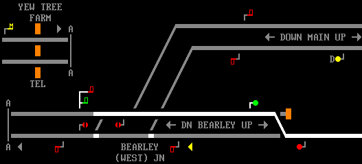
Semaphore signalling, at Henley in Arden. Beyond the last stop signals, an Absolute Block section exists to Shirley on the Up, and Bearley Jn on the Down. Only look at the signals for the Up and Down Main at the moment. Note the red stop signals, and yellow distant signals. The Up Main has a mechanical distant, while the one on the Down has been replaced by a colour light.
If it isn’t possible to clear all the stop signals for a train, they must all be maintained at danger until the train approaches. When it is nearly at a stand at the first stop signal, the signal may be cleared and the train will proceed to the next one, which again may be cleared as it approaches. This is to ensure the driver is in control of the train and well aware that the block section ahead is occupied. Of course, if the block section ahead becomes clear, all the remaining signals ahead of the train may be cleared immediately. In some simulations, this method of working is automatically enforced by the simulation regardless of when the routes are set, in others it is up to you to follow the rules if you wish.
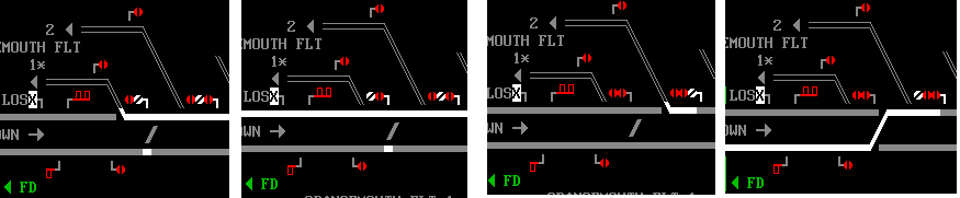
The Saltley simulation enforces the rules! The last stop signal (known as the section signal) cannot be cleared (perhaps there is a train in the section ahead), therefore the first two are held at red.
Until a train comes to a stand, at which point the signals clear individually. In real life, of course, the signaller cannot set the route in advance like we did (the signal arm is controlled directly by a wire from a lever in the box) this is simply the developer fitting an IECC simulator around a mechanical installation.
We can clear all the stop signals, so the Distant signal can also be cleared. In SimSig, this is normally done automatically.
Shunt Signals
Shunt signals consist either of a version of the standard stop signal arm (this reduction in size is not shown in SimSig) mounted on a post, or as a ground-mounted disc, which is horizontal at ‘Danger’ and at 45° when clear. In SimSig, they will show red and white for danger and clear respectively, as usual. As with colour lights, shunt signals may be combined with main signals. The way in which this is drawn varies- sometimes it will be shown on its own ‘arm’, at other times it is underneath the main signal arm. This reflects the variety of ways semaphore signals were constructed in reality.
As usual, routes can be set from shunt signals to other shunt signals, or from shunt signals to main signals. As with colour lights, routes can only be set from a main signal to a shunt signal if the main signal incorporates a shunt signal.
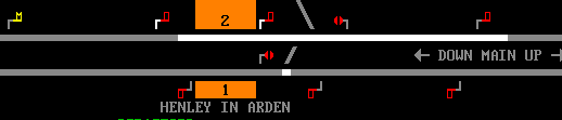
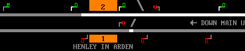
Henley in Arden, with two disc-style shunt signals cleared, and another two at Danger.
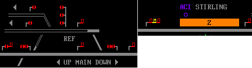
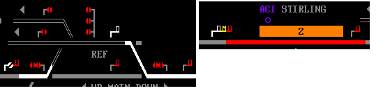
A variety of shunt arms at Laurencekirk and Stirling. At Laurencekirk, we see a shunt arm combined with a main arm, and a shunt version of a main arm- note that this arm would be smaller in real life. In all cases, the show the usual white indication of a shunt signal when cleared. At Stirling, we see a different style of shunt arm combined with main, in this case used for permissive working at Platform 2. The final set of pictures shows the location of the main signal arms in the layouts. The distant arm at Stirling is not relevant to this section and can be ignored. See 'Short Sections' below for an explanation of why it's there.
Running Shunts
In reality, the signalman would need to clear the shunt signal first, then the main signal preceeding it. In SimSig, the route is set in exactly the same way as in colour light areas, i.e. from main signal to main signal.
A Running Shunt at Dunblane, semaphore-style. Simply set the route from the first main signal to the next main signal, as you would in a colour-light area. Note also the symbol for a Limit of Shunt board in semaphore areas. The first signal is a junction signal, explained below.
Junction Signals
At junctions, each available route is provided with its own arm (unless some other form of route indicator was provided), which can result in some rather magnificent arrangements! As you’d expect, the leftmost signal applies to the leftmost route, and so on. Shunt signals vary- sometimes one arm or disc is provided for each route, at other locations only one arm/disc is provided. Where more than one disc/arm is provided, they are often stacked on top of each other: the topmost disc/arm applies to the leftmost route.
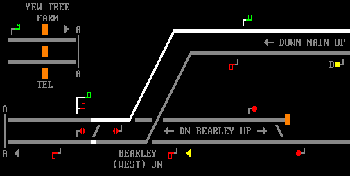
Junction signals at Bearley West Jn, with one arm for each route. The arm for the higher-speed route, towards the Up Main, is higher than the one for the (slower) Up Brearley. Note that the distant signal remains at caution in the second picture, even though all the signals are clear: see below for details. Also be aware that the section of the track containing the distant is elsewhere in the actual simulation, the track layout image has been manipulated to save space.
Fun with shunts at Fouldubs Jn. This neatly illustrates the rules: Topmost disc applies to leftmost route, and so on.
Approach control
A form of approach control is applied at junctions, just like with colour lights. Usually, the distant signal can only be cleared when the stop signals for the fastest route are cleared- for a slower diverging route, the distant is maintained at caution, to ensure the driver reduces speed. Occasionally, a ‘splitting distant’ is provided, where a distant signal arm is provided for both the main and diverging route.
For sidings, you may have to wait until a train enters the track circuit approaching the signal before you can set the route into the siding. This is just the same as you see in colour light areas, the only difference being that in colour light areas you can set the route and the signal clear later; obviously this isn’t possible with semaphores.
Short sections
Where two signalboxes are close together, the distant signal of the box ahead may be mounted on the same post as the last signal of the first box, as illustrated above. If the boxes are very close together, an ‘inner’ and ‘outer’ distant may be provided, the ‘outer’ distant giving sufficient braking distance for the driver to stop at the home signal.
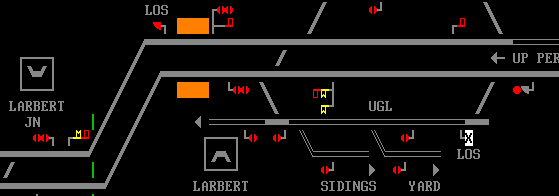
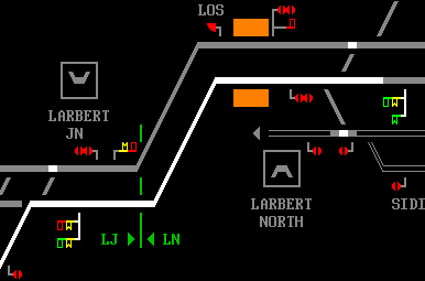
Larbert Jn, and Larbert North. Because the section is so short, the Down distant for Larbert North box is mounted on the same post as Larbert Junction’s last stop signal. In the opposite direction, it’s a bit more complicated: Larbert Jn has a split distant. The left hand distant will clear if the signals on the left hand route are clear, the right hand distant will clear if the right hand route signals are clear. The signals are mechanically locked such that the distant can only show clear if the stop signal is also clear. It is, of course, perfectly possible for the stop signal to be clear and the distant at caution- the driver will simply slow down ready to stop at the next signal, as usual.
In fact, the section between Larbert Jn and Larbert North is so short that both of Larbert Jn’s stop signals carry distant signals for Larbert. The principle is the same: the distants will clear if Larbert North can clear all the stop signals. Drivers must use their route knowledge to know which box the distant applies to, and, if they’re at caution, where the danger signal will be!
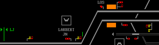
Larbert North can clear its stop signals for the left hand route, so the left hand distant has cleared. The sections to the next boxes are, again, short ones, so their distant signals are mounted beneath the stop signals at Larbert. In this case, the next box can’t clear their signals so the distant remains at caution.
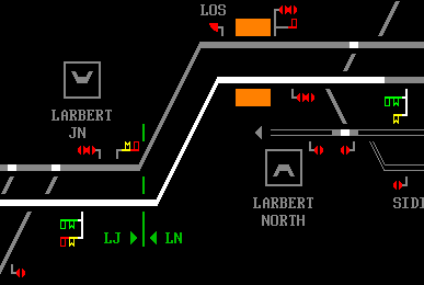
Right hand signals at Larbert Jn cleared, right hand distant at Larbert North clears. This time, the box ahead can clear their stop signals, so the distant also clears.
If the above is a bit confusing, don’t panic! The Larbert area is by far the most complex semaphore area represented in terms of distant signals. It becomes much easier when you play for yourself.
Miscellaneous
Intermediate Block Sections (IBS)
In order to run more trains, block sections have to be shorter. On many lines, this resulted in tiny ‘break section’ boxes, which controlled one stop and one distant signal in each direction, serving no other purpose than to shorten the block lengths. This wasn’t particularly economical, so with track circuiting becoming practical, IB sections became more common. These signals were controlled from the box in rear, with the line from the first box’s starter signal to the overlap of the IBS fitted with track circuits. The section from the IBS to the next box was a standard Absolute Block section. This reduced the number of signallers required to work the line.
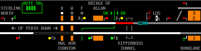
There is an IB signal in each direction at Bridge of Allan, between Stirling North and Dunblane. The signal on the Down line is controlled by Stirling, and the signal on the Up is controlled by Dunblane, as indicated by the green workstation boundaries. On the Up line, there is a train occupying the section on the Down line. However, the line to the IB signal is clear, so Stirling North can clear the stop and distant signals adjacent to the box for a following train. The IB signal will be cleared when 2Z00 arrives in Dunblane station. In the Up direction, the section is clear to Stirling North, so both the local and IBS signals controlled by Dunblane can be cleared.
Track circuiting
When they were first invented, track circuits were an expensive luxury, and many boxes had only a few, if any. Track circuits were gradually provided more frequently, and lines were converted to continuous track circuiting and colour light signalling, as seen in most SimSig simulations. As semaphore controlled areas are, by definition, unmodernised, you’ll find that track circuits are a lot scarcer than in other simulations.
Available Routes
As each route must be provided with its own signal arm, and all facing points on the route provided with facing point locks, there are many routes which, although physically possible, are not allowed by the interlocking. Hence, you’ll find that certain locations can only be accessed via shunt signals, which do not have the same requirement. The problem stems from a need to keep the number of levers and amount of interlocking as low as practicable- an all-singing all-dancing layout would be very expensive to design, install and maintain.
Last edited by headshot119 on 17/12/2018 at 16:27